
China Moneypro
UAV Gimbal Thermal Imager Integration
Master thermal imager UAV gimbal integration. Expert guide on SWaP-C optimization, vibration isolation, and EO/IR payload engineering for drone systems.
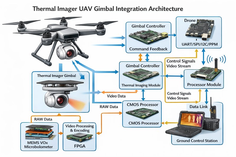
Successfully executing a thermal imager UAV gimbal integration defines the operational capability of modern airborne electro-optical/infrared (EO/IR) systems. Drone payload engineers face significant challenges when mounting highly sensitive infrared cores into dynamic, multi-axis stabilized pods. Therefore, mastering the mechanical, electrical, and thermal variables is non-negotiable for achieving crystal-clear long-wave infrared (LWIR) imagery during flight.
To successfully integrate a thermal imager into a UAV gimbal, engineers must balance SWaP-C constraints with rigorous vibration isolation and precise center-of-gravity alignment. Optimal integration requires matching the uncooled microbolometer’s electrical interfaces with the gimbal’s slip ring while implementing dynamic PID stabilization control to eliminate micro-jitter.
Key Takeaways
- Center of Gravity (CG) alignment is critical; even a 1mm offset can degrade PID control loop performance.
- Uncooled VOx microbolometers require dedicated thermal dissipation paths to maintain optimal NETD parameters inside sealed gimbal pods.
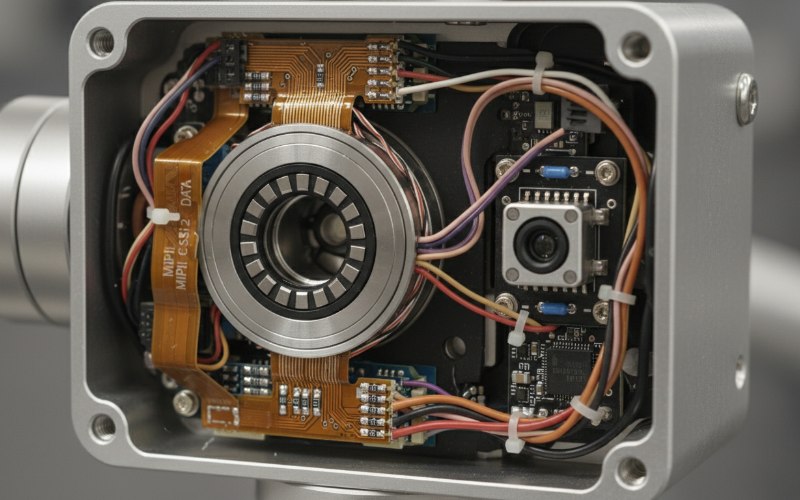
- Routing high-speed MIPI CSI-2 or LVDS video signals through continuous 360-degree slip rings demands strict impedance control and shielding.
- The Inertial Measurement Unit (IMU) must be rigidly coupled to the thermal core’s optical axis to prevent phase lag during stabilization.
The Core of Thermal Imager UAV Gimbal Integration
The fundamental goal of thermal imager UAV gimbal integration is to isolate the infrared sensor from airframe vibrations while allowing precise targeting and tracking. Modern uncooled Vanadium Oxide (VOx) microbolometers boast pixel pitches as small as 10µm to 12µm. Consequently, any mechanical jitter directly translates into pixel blur, effectively nullifying the advantages of high-resolution thermal cores. Engineers must approach this integration holistically. They must consider the payload’s mass distribution, the routing of power and data cables, and the environmental sealing required to protect sensitive optoelectronics at high altitudes.
SWaP-C Optimization in EO/IR Payload Engineering
Size, Weight, Power, and Cost (SWaP-C) dictate every decision in drone payload engineering. When you design EO/IR payload modules, reducing the overall footprint directly increases the UAV’s flight time and operational envelope.
Weight Distribution and Gimbal Balance
Perfect static balance is the prerequisite for optimal dynamic stabilization. If the thermal core is mounted off-axis, the gimbal’s brushless DC (BLDC) motors must exert continuous holding torque to maintain the camera’s level. This asymmetric load drastically increases power consumption and introduces thermal noise into the motor stators. Therefore, engineers must use 3D CAD modeling to align the thermal imager’s optical axis precisely with the gimbal’s pitch and roll axes. Counterweights should be minimized; instead, internal components like the processing boards and lens assemblies should be strategically placed to achieve a natural center of gravity.
Thermal Dissipation Within Sealed Pods
Although we predominantly use uncooled IR detectors for UAVs, these sensors still generate heat. VOx microbolometers perform best when their internal temperature is strictly regulated. If the ambient temperature inside the sealed gimbal sphere rises, the sensor’s Noise Equivalent Temperature Difference (NETD) degrades, leading to grainy, washed-out imagery. Engineers must design conductive thermal paths utilizing graphite thermal pads or custom aluminum heat sinks. These conductive elements transfer heat from the focal plane array (FPA) baseplate directly to the external aluminum gimbal housing, which acts as a passive radiator in the aircraft’s slipstream.
Mechanical Mounting and Vibration Isolation
Airframes generate a complex spectrum of high-frequency and low-frequency vibrations from propellers and motors. Without robust isolation, these vibrations cause structural resonance within the gimbal payload. Complying with aerospace vibration protocols, such as those found in MIL-STD-810G, is essential for professional deployment.
Strategic IMU Placement
The payload Inertial Measurement Unit (IMU) is the heart of the stabilization control loop. A common mistake is mounting the IMU on the gimbal frame rather than the camera module itself. The IMU must be rigidly coupled to the thermal core bracket. This ensures that the gyroscope and accelerometer measure the exact angular rates experienced by the optical path. Any mechanical flex between the IMU and the lens assembly introduces phase lag, which confuses the Proportional-Integral-Derivative (PID) controller and results in high-frequency oscillations known as micro-jitter.
| Video Interface | Bandwidth | Integration Complexity | Best Use Case in Gimbals |
|---|---|---|---|
| Analog (CVBS) | Low | Low | Legacy systems, low-resolution targeting. |
| Parallel (CMOS) | Medium | Medium | Direct board-to-board integration, short trace lengths. |
| LVDS | High | High | High-resolution thermal cores, long cable runs across slip rings. |
| MIPI CSI-2 | Very High | Very High | Next-generation smart payloads, requires strict impedance matching. |
Electrical Integration and Data Transmission
Routing power and high-speed data across rotating joints is a profound mechanical and electrical challenge. UAV gimbals require continuous 360-degree pan rotation, which mandates the use of electrical slip rings.
Routing High-Speed Video Through Slip Rings
Standard thermal cores output video via LVDS or MIPI CSI-2 interfaces. Passing these high-frequency differential signals through a mechanical slip ring introduces insertion loss, crosstalk, and impedance mismatches. To mitigate data corruption, engineers must utilize specialized high-speed capsule slip rings designed for gigabit transmission. Furthermore, utilizing flexible printed circuits (FPC) with dedicated ground planes on either side of the signal traces provides essential electromagnetic interference (EMI) shielding. Careful attention to cable routing minimizes torsion and extends the lifecycle of the payload.
Field Experience: Debugging Micro-Vibrations
In my experience integrating a 640×512 VOx thermal core into a Class 1 UAV tactical gimbal, I encountered a severe anomaly. The imagery looked pristine on the test bench, but during flight operations, the Non-Uniformity Correction (NUC) mechanical shutter kept jamming. Initially, we suspected a firmware glitch. However, after deploying a laser vibrometer, we discovered a 120Hz harmonic resonance stemming from the drone’s carbon-fiber booms. This high-frequency vibration was passing right through our standard rubber dampers, causing the ultra-lightweight shutter flag to physically resonate and bind against the lens housing.
We resolved this by redesigning the payload isolation plate. We transitioned from generic rubber grommets to custom wire rope isolators tuned specifically to dampen the 100Hz to 150Hz frequency band. Additionally, we implemented a dynamic PID notch filter in the gimbal controller to electronically mask the residual resonance. This hands-on integration process proves that theoretical CAD models must always be validated with aggressive, real-world flight testing.
Firmware, Calibration, and Dynamic NUC
Once the hardware is physically secured, payload engineers must address the software interface. Uncooled thermal imagers require periodic Flat Field Correction (FFC) or NUC to clear thermal drift and sensor noise. During an FFC event, a mechanical shutter drops over the sensor, freezing the video feed for roughly 0.5 to 1 second.
For UAV operators conducting high-speed target tracking, a frozen frame is disastrous. Engineers must integrate the thermal core’s telemetry via serial communication (UART/RS-232) to take control of the NUC timing. Advanced integration involves programming the gimbal controller to trigger FFC events only during waypoint transitions or when the target lock is highly stable. Moreover, adopting shutterless thermal imaging modules is becoming highly favorable, as they utilize advanced algorithms to perform dynamic NUC without interrupting the video feed.
Conclusion
Executing a flawless thermal imager UAV gimbal integration requires rigorous adherence to mechanical balancing, electrical shielding, and thermal management protocols. By addressing weight distribution, deploying robust vibration isolators, and managing high-speed video routing through slip rings, engineers can unlock the full potential of airborne infrared systems. You cannot compromise on these engineering fundamentals if you want to deliver military-grade or commercial-grade aerial imaging. Ensure your next project utilizes strict PID tuning and optimized SWaP-C architectures.
If you are ready to elevate your drone payload design, schedule an Equipment Consultation today to review your exact thermal imager UAV gimbal integration requirements.
FAQ
How do you balance a thermal imager in a UAV gimbal?
Balancing a thermal imager requires aligning the sensor’s center of gravity precisely with the gimbal’s pitch and roll axes using 3D CAD modeling. Engineers strategically place internal components like processing boards and lenses to achieve natural equilibrium without relying heavily on counterweights, which add unnecessary mass to the payload.
Why is vibration isolation critical for thermal payloads?
Vibration isolation is critical because uncooled microbolometers have tiny pixel pitches, commonly between 10µm and 12µm. High-frequency airframe vibrations cause micro-jitter, which blurs the long-wave infrared imagery and drastically degrades the overall spatial resolution. Custom-tuned wire rope isolators and specialized dampening materials are necessary to filter out these disruptive operational frequencies.
What is the best video interface for drone thermal cameras?
For modern high-resolution thermal cores, MIPI CSI-2 is highly preferred due to its massive bandwidth and minimal power footprint. However, for older architectures or integrations requiring long, complex cable routing through continuous 360-degree slip rings, LVDS remains widely utilized due to its reliable and robust differential signaling capabilities.
How does thermal dissipation work in a sealed UAV pod?
Thermal dissipation in a completely sealed UAV pod relies primarily on conductive cooling. Payload engineers implement graphite thermal pads or custom-machined aluminum heat sinks to bridge the heat-generating focal plane array to the external metallic gimbal housing. The external casing then passively radiates the accumulated heat directly into the ambient atmosphere aided by the drone’s aerodynamic slipstream.