
China Moneypro
What Is Night VisionTechnology: Image Intensification vs Thermal Imaging
Explore technical differences between I2 and thermal night vision. Compare NETD, spectral ranges, and integration requirements for security and defense systems.
Key Takeaways for System Integrators
- Distinct Technologies: “Night Vision” encompasses two distinct physics principles: Image Intensification (I2), which amplifies photons in the Near-Infrared (NIR) band, and Thermal Imaging, which detects heat signatures in the Long-Wave Infrared (LWIR) spectrum.
- Sensor Performance: Modern Gen 3 I2 tubes utilize Gallium Arsenide (GaAs) photocathodes for high FOM (Figure of Merit), while uncooled VOx thermal detectors now achieve NETD <30mK sensitivities.
- Operational Constraints: I2 requires some ambient light (moon/stars) and struggles in fog; Thermal operates in zero light and penetrates atmospheric obscurants but typically offers lower resolution.
- Integration Trends: The industry is shifting toward Sensor Fusion, combining low-light CMOS or I2 with high-resolution thermal cores to maximize situational awareness via overlay algorithms.
For B2B system integrators designing payloads for UAVs, border security systems, or automotive ADAS, the term “Night Vision” is often an umbrella categorization. However, selecting the correct electro-optical (EO/IR) architecture requires a rigorous engineering analysis of spectral ranges, detector sensitivity, and environmental operating conditions. This guide dissects the technical distinctions between Image Intensification (I2) and Thermal Imaging, focusing on integration specifications and performance metrics.
The Physics of Night Vision: Spectral Ranges Defined
To understand the limitations and capabilities of night vision hardware, one must first map the technologies to the electromagnetic spectrum. The human eye detects visible light between 0.4 and 0.7 microns (μm). Night vision technologies extend this perception into the infrared bands.
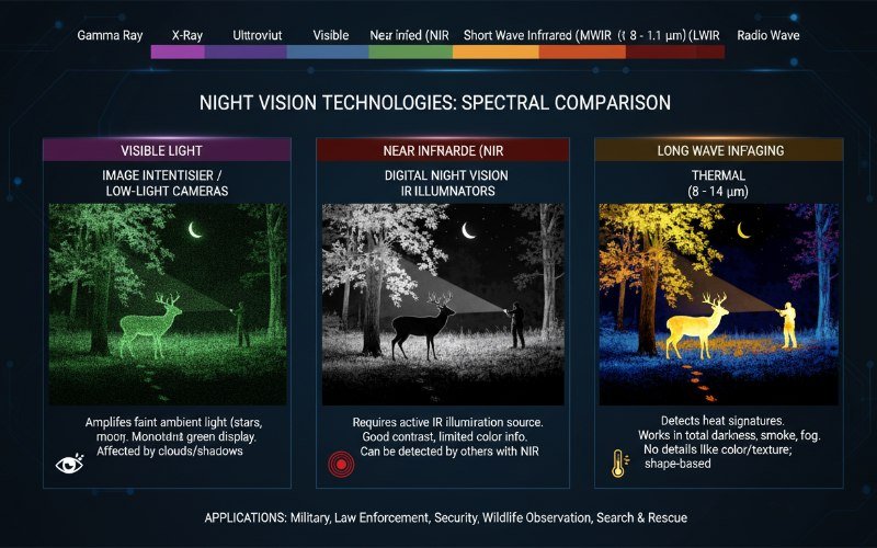
1. Near-Infrared (NIR) / Image Intensification (0.7 – 1.1 μm):
Traditional night vision (I2) operates here. It relies on reflected photons from ambient sources like starlight or moonlight. It behaves similarly to the human eye regarding reflection and contrast but with amplified gain.
2. Long-Wave Infrared (LWIR) / Thermal Imaging (7.5 – 13.5 μm):
This band detects thermal radiation emitted directly by objects. Because it does not rely on reflected light, LWIR sensors function in absolute darkness and are immune to the “blooming” effects that bright lights cause in I2 systems.
Image Intensification (I2): Architecture and Generations
Image Intensification (I2) is what is historically referred to as “Night Vision Devices” (NVDs). The core component is the Image Intensifier Tube (IIT), a vacuum tube that converts photons to electrons, amplifies them, and converts them back to photons.
The Microchannel Plate (MCP) Mechanism
Modern I2 systems (Gen 2 and Gen 3) utilize a Microchannel Plate (MCP). The process involves three stages:
- Photocathode: Incoming photons strike the photocathode, releasing electrons via the photoelectric effect.
- MCP Amplification: Electrons enter the MCP—a glass disk with millions of microscopic channels. A high voltage gradient accelerates the electrons, causing secondary emission cascades. A single electron can generate thousands of secondary electrons.
- Phosphor Screen: The amplified electron avalanche strikes a phosphor screen (typically P43 green or P45 white phosphor), converting energy back into visible light.
Generation 3 vs. 4G Technology
For high-end integration, understanding the “Generation” is critical for predicting Signal-to-Noise Ratio (SNR) and resolution.
- Gen 3 (GaAs): Uses a Gallium Arsenide photocathode, which is significantly more sensitive in the NIR spectrum than the Multi-Alkali cathodes of Gen 2. Gen 3 tubes typically feature an Ion Barrier Film to protect the cathode, though this slightly reduces SNR.
- High-FOM (4G/Unfilmed): Modern “4G” or “Filmless” tubes remove the ion barrier or optimize the gating, resulting in higher Figure of Merit (FOM) scores (often >2300) and wider spectral sensitivity, pushing into the UV and higher NIR ranges.
Infrared Thermal Imaging: The Emissive Solution
Unlike I2, thermal imaging does not require any ambient light. For industrial monitoring, perimeter security, and search and rescue, thermal is often superior due to its high contrast against cold backgrounds.
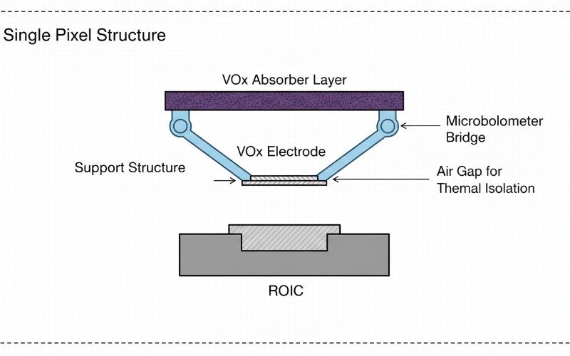
Uncooled VOx Microbolometers
The standard for most commercial and defense applications is the uncooled Vanadium Oxide (VOx) microbolometer. These infrared detectors operate at ambient temperatures, eliminating the need for cryogenic cooling (Stirling coolers), which optimizes SWaP-C (Size, Weight, Power, and Cost).
Key Performance Indicators (KPIs):
- Pixel Pitch: The industry is migrating from 17μm to 12μm pixel pitch. A 12μm pitch allows for smaller focal length lenses to achieve the same magnification, significantly reducing the weight of optical assemblies in drone payloads.
- NETD (Thermal Sensitivity): Noise Equivalent Temperature Difference measures the smallest temperature difference a sensor can distinguish. High-end industrial modules now offer NETD <30mK or even <20mK, providing crisp details in low-contrast scenes (e.g., a person standing in front of a heated wall).
- Resolution: Common formats include QVGA (384×288), VGA (640×512), and HD (1280×1024).
Comparative Analysis: I2 vs Thermal for Integrators
When selecting a module for integration into a gimbal or security camera, the following comparison highlights operational trade-offs.
| Feature | Image Intensification (I2) | Thermal Imaging (LWIR) |
|---|---|---|
| Detection Principle | Photon Amplification (Reflected Light) | Heat Radiation (Emissive) |
| Operating Spectrum | 0.7μm – 1.1μm (NIR) | 7.5μm – 13.5μm (LWIR) |
| Zero Light Capability | No (Needs IR illuminator in 0 lux) | Yes (Total Darkness) |
| Atmospheric Penetration | Low (Scatters in fog/smoke) | High (Penetrates smoke/light fog) |
| Facial Recognition | High (Visual details preserved) | Low (Shows heat patterns, not pigment) |
| Glass Transparency | Can see through glass | Cannot see through standard glass |
| Cost | Moderate to High (Export Controlled) | Scalable (Low to High) |
Sensor Fusion: The Future of Night Vision
For mission-critical applications, reliance on a single spectral band is becoming obsolete. Leading security systems and UAV payloads now employ Sensor Fusion.
This architecture combines a low-light CMOS sensor (digital night vision) with a high-resolution thermal core. An onboard FPGA or SoC processes both streams, overlaying the high-contrast thermal edges onto the detailed visible image. This provides the “best of both worlds”: the identification capability of visible light (reading license plates, recognizing faces) with the detection capability of thermal (spotting a camouflaged target).
Integration Challenges: SWaP and Interfaces
Integrators must consider the electrical and mechanical interfaces when choosing night vision modules:
- Video Interfaces: While analog (PAL/NTSC) remains common for low-latency FPV, digital interfaces like MIPI CSI-2, CameraLink, and USB 3.0 are required for high-bandwidth raw data transfer necessary for AI image processing.
- Synchronization: Multispectral systems require hardware synchronization to align frames from the thermal and visible sensors for accurate fusion.
- Ruggedization: Modules intended for defense or automotive use must meet MIL-STD-810 standards for shock and vibration.
Frequently Asked Questions
Can thermal cameras see through walls?
What is the lifespan of an Image Intensifier Tube?
Why is NETD important for system integrators?
Does thermal imaging work in daylight?