
China Moneypro
Thermal Scope vs Viewer vs Monocular Selection Guide
Compare thermal scopes, viewers, and monoculars. Expert engineering analysis on sensor resolution, NETD specs, and operational use cases for precision optics.
This article is part of our Comparisons & Buying Guides section. For a complete overview, visit our Knowledge Hub guide.
Selecting the correct infrared imaging device requires a deep understanding of optoelectronic architecture and mission requirements. The distinction between a thermal scope, a thermal viewer (clip-on), and a thermal monocular goes beyond form factor. It involves critical differences in sensor calibration, recoil resistance, and optical collimation. This guide breaks down the engineering nuances of each device type to ensure optimal procurement decisions.
Key Takeaways
- Thermal Monoculars are strictly for handheld observation and cannot withstand weapon recoil or maintain a zero.
- Thermal Scopes replace day optics entirely and feature integrated reticles, shock-proof housings, and digital zeroing systems.
- Thermal Clip-On Viewers mount in front of existing day optics to convert glass scopes into thermal systems without requiring re-zeroing.
- Sensor Specs Matter regardless of form factor. Look for 12μm pixel pitch and NETD <35mK for superior thermal sensitivity.
Core Technology And Sensor Architecture
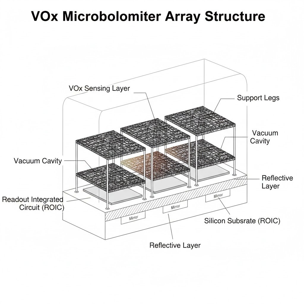
At the heart of every thermal device lies the Focal Plane Array (FPA). Whether the device is a monocular, scope, or clip-on viewer, the underlying physics remains consistent. These systems utilize Uncooled VOx (Vanadium Oxide) microbolometers to detect infrared radiation in the Long-Wave Infrared (LWIR) spectrum, typically between 8 to 14 microns.
The primary differentiation arises in the backend electronics and the optical assembly. While a monocular prioritizes power efficiency and wide fields of view for scanning, a dedicated thermal scope demands high-speed image processing to minimize latency during rapid movement. The difference is not just in the casing but in the firmware algorithms that govern image enhancement and reticle stability.
Thermal Monoculars For Handheld Observation
A thermal monocular is an optoelectronic device designed exclusively for handheld use. From an engineering standpoint, the chassis is optimized for ergonomics and weight reduction rather than impact resistance. These units act as the “spotter” in a tactical or hunting scenario.
Optical Design Limitations
The ocular lens of a monocular is designed for direct eye coupling. Unlike riflescopes which require varying eye relief to prevent injury from recoil, a monocular eyepiece usually has very short eye relief. Furthermore, the firmware lacks the requisite “zeroing” coordinates X and Y. Even if one were to jury-rig a monocular to a rail system, the shock from the discharge would likely fracture the solder joints on the PCB or misalign the germanium objective lens, as these units are rarely rated for forces exceeding 100 Gs.
Primary Use Cases
Monoculars are superior for area scanning. An operator can scan a 180-degree field of view significantly faster with a handheld unit than by maneuvering a rifle-mounted optic. High-end models often feature Laser Range Finders (LRF) and Wi-Fi transmission modules to stream data to a command center or mobile device.
Dedicated Thermal Riflescopes For Precision Shooting
A dedicated thermal scope is a standalone targeting system. It replaces the traditional glass optic entirely. The engineering focus here shifts heavily toward structural integrity and reticle precision. These devices must survive repeated shock impulses often exceeding 1000 Gs (depending on the caliber rating).
Digital Zeroing Architecture
Unlike glass scopes that move physical erector tubes, thermal scopes utilize a digital zoom and reticle overlay. The “zeroing” process involves shifting the pixel coordinates of the reticle on the OLED or AMOLED display to align with the barrel’s Point of Impact (POI). This allows for advanced features such as “One-Shot Zero” where the software calculates the offset and auto-corrects the reticle position.
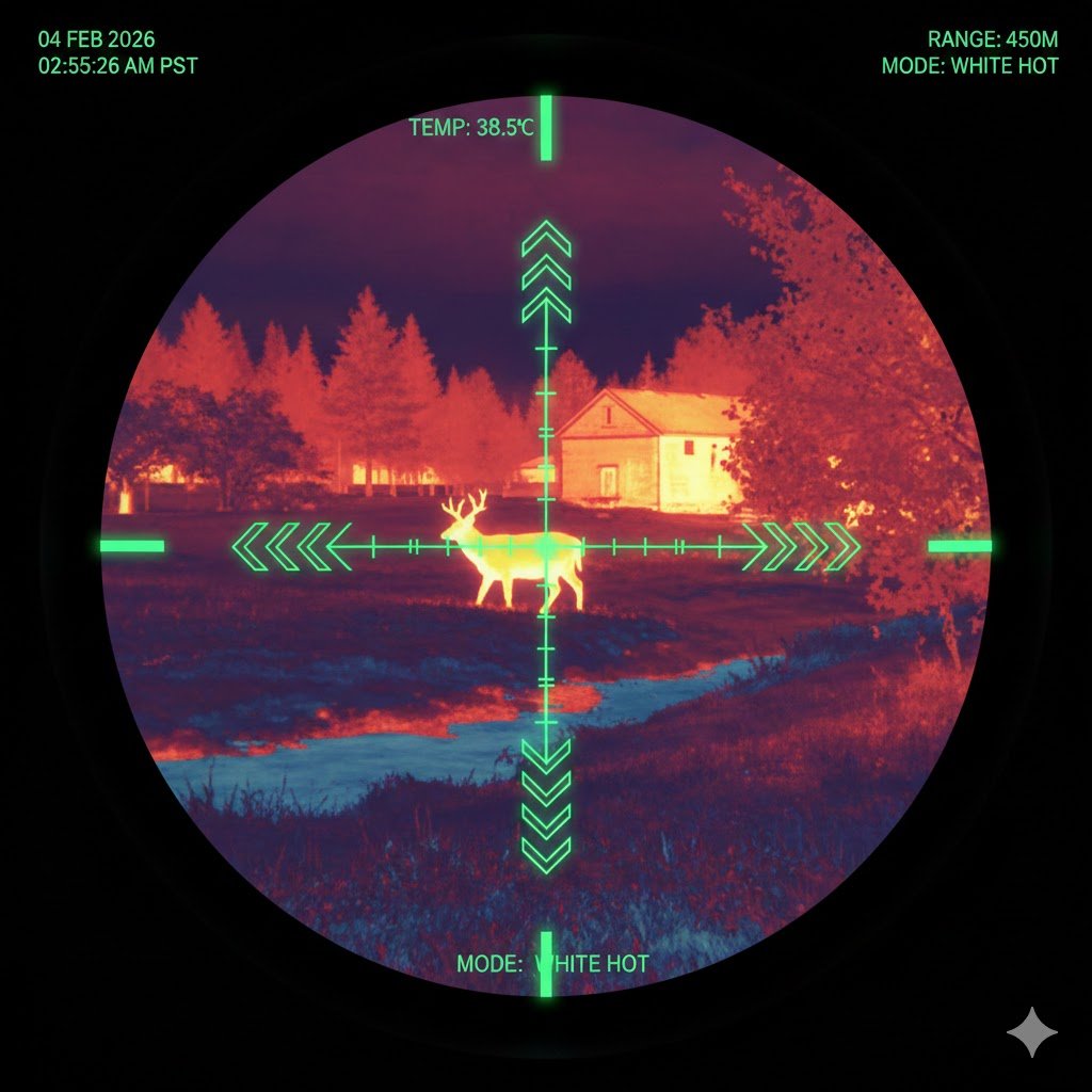
Image Processing for Engagement
Latency is the enemy of accuracy. Thermal scopes utilize high refresh rates, typically 50Hz, to ensure smooth imaging of moving targets. Lower refresh rates (9Hz or 30Hz) can result in “lag” or image tearing, which causes the shooter to miss. The image processing engine also prioritizes contrast enhancement (NETD factors) to distinguish targets from background clutter.
Thermal Clip On Viewers For Versatile Deployment
The thermal clip-on (or front attachment) is perhaps the most optically complex device of the three. It mounts directly to the objective bell of a day scope or on a rail in front of it. Its purpose is to convert the day scope into a thermal imaging system.
The Collimation Challenge
The defining engineering characteristic of a clip-on is collimation. The device captures the thermal image and displays it on a rear screen. The optical train must be perfectly aligned so that the image on the screen appears at infinity (1.0x magnification) to the day scope. If the collimation is off by even a fraction of a degree, the Point of Impact will shift when the device is attached. High-quality clip-ons are factory calibrated to ensure that no re-zeroing of the day optic is required.
Advantages Over Dedicated Scopes
Clip-ons offer modularity. A user can utilize high-quality glass optics for daytime identification and seamlessly transition to thermal capability at night without removing the day scope. This preserves the eye relief, magnification dial, and reticle holdovers of the trusted day optic.
Technical Comparison Matrix
To assist in the selection process, the following table contrasts the critical engineering specifications and operational capabilities of the three form factors.
| Feature | Thermal Monocular | Thermal Scope | Thermal Clip-On Viewer |
|---|---|---|---|
| Primary Function | Observation & Scanning | Targeting & Engagement | Day Optic Conversion |
| Reticle System | None | Digital Overlay | Utilizes Day Scope Reticle |
| Recoil Rating | Low / None | High (>1000G) | High (>1000G) |
| Zeroing Required | N/A | Yes (Digital) | No (Factory Collimated) |
| Magnification | Fixed Optical + Digital | Fixed Optical + Digital | 1x (Unity) Optical |
| Mounting Interface | Tripod / Lanyard | Picatinny / Weaver Rail | Objective Bell / Rail |
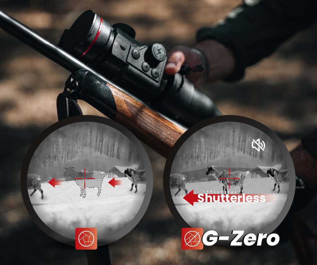
| Start-Up Time | Instant to 3s | 3s to 5s | 3s to 5s |
Critical Specifications For Performance
Regardless of which form factor you select, the performance is dictated by three primary specifications. Ignoring these will result in subpar imaging regardless of the housing type.
NETD Sensitivity
Noise Equivalent Temperature Difference (NETD) measures the sensor’s ability to distinguish small temperature differences. A lower number indicates higher sensitivity. Professional-grade devices now feature NETD <25mK or <35mK. In conditions with low thermal contrast—such as rain, fog, or cold mornings—a low NETD is essential for generating a usable image.
Pixel Pitch and Resolution
Modern sensors have moved from 17μm (microns) to 12μm pixel pitch. The smaller pixel pitch allows for higher magnification with smaller objective lenses. Standard resolutions are 384×288 (entry to mid-range) and 640×512 (high-end). For long-range identification, 640×512 resolution is strongly recommended to prevent pixelation at high digital zoom levels.
Frequently Asked Questions
Common questions regarding the interchangeability and application of thermal devices.
Can a thermal monocular be used as a scope
Does a thermal clip on affect the zero of my day scope
What is the main advantage of a dedicated thermal scope over a clip on
Why is 50Hz refresh rate important