
China Moneypro
Thermal Imaging Principles and The Science of Infrared Detection
Explore the core thermal imaging principles driving modern infrared technology. Learn about VOx microbolometers, NETD sensitivity, and optics physics.
This article is part of our Infrared & Thermal Technology section. For a complete overview, visit our Knowledge Hub guide.
Thermal imaging stands as one of the most significant advancements in optoelectronics and sensing technology. Unlike traditional visible light cameras that rely on reflected photons, thermal imaging systems detect heat signatures emitted directly from objects. This capability allows for visibility in total darkness, through atmospheric obscurants like smoke or fog, and provides critical temperature data for industrial analysis.
Understanding thermal imaging principles requires a deep dive into infrared physics, sensor architecture, and signal processing. For engineers, procurement officers, and technology enthusiasts, grasping the mechanics behind Long-Wave Infrared (LWIR) and Mid-Wave Infrared (MWIR) detection is essential for selecting the right equipment. This article details the engineering foundations that make thermal visualization possible.
Key Takeaways on Infrared Technology
- Infrared Radiation Basics
All objects above absolute zero emit infrared energy, which thermal sensors convert into electrical signals. - Detector Types
Uncooled VOx microbolometers dominate commercial markets, while cooled photon detectors serve high-speed scientific and defense applications. - Role of Optics
Standard glass blocks infrared radiation, necessitating lenses made from Germanium, Silicon, or Chalcogenide glass. - Critical Metrics
NETD (Noise Equivalent Temperature Difference) measures a sensor’s thermal sensitivity, with lower values indicating superior performance.
The Physics of Infrared Radiation
The foundation of thermal imaging lies in the electromagnetic spectrum. The infrared band sits between the visible light spectrum and microwave radiation. While the human eye can perceive wavelengths from approximately 0.4 to 0.7 micrometers (μm), thermal imaging generally operates in longer wavelengths.
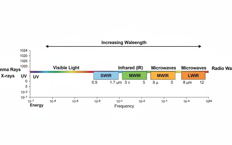
Spectral Bands in Thermal Imaging
Infrared systems do not operate across the entire infrared spectrum simultaneously. Atmospheric windows—ranges where the Earth’s atmosphere transmits infrared radiation without significant absorption—dictate detector design. The three primary bands include the following.
- Short-Wave Infrared (SWIR)
Range: 0.9μm to 1.7μm. SWIR behaves similarly to visible light and requires reflected light (starlight or nightglow) to create images. - Mid-Wave Infrared (MWIR)
Range: 3μm to 5μm. This band is highly sensitive to high-temperature targets and is often used in cooled detectors for long-range surveillance and gas leak detection. - Long-Wave Infrared (LWIR)
Range: 8μm to 14μm. This is the primary band for uncooled thermal imaging. Most terrestrial objects emit the majority of their thermal energy in this range, making it ideal for passive monitoring.
Emissivity and Blackbody Physics
To interpret thermal images accurately, one must understand emissivity. An ideal object that absorbs and emits all radiation perfectly is known as a blackbody. However, in the real world, objects are selective radiators. Emissivity is a ratio (from 0 to 1) describing how efficiently an object emits thermal energy compared to a blackbody.
High-emissivity materials like human skin, concrete, and wood (0.90–0.98) are easy to measure. Low-emissivity materials like polished aluminum or stainless steel (0.10–0.20) reflect ambient temperature rather than emitting their own, creating challenges in thermography.
Core Components of a Thermal Camera
A thermal camera functions essentially as a radiometer, measuring the intensity of radiation entering the aperture. The system comprises an optical lens, a detector (Focal Plane Array), and signal processing electronics.
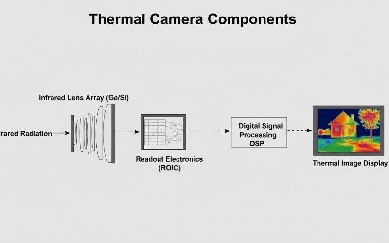
Infrared Optics and Lens Materials
Standard silicate glass is opaque to LWIR radiation. Consequently, thermal lenses utilize exotic materials such as Germanium (Ge), Zinc Selenide (ZnSe), or Chalcogenide glasses. Germanium is the most common material for high-performance LWIR systems due to its high refractive index, which allows for thinner lens profiles. However, Germanium is expensive and requires specialized anti-reflective (AR) coatings, usually Diamond-Like Carbon (DLC), to maximize transmission and protect the soft surface.
The Focal Plane Array (FPA)
The FPA acts as the “retina” of the thermal camera. It consists of a two-dimensional array of pixels (microbolometers) that react to incoming infrared energy. As the infrared photons strike the pixel material, they cause a measurable physical change. The Readout Integrated Circuit (ROIC) underneath the pixel array converts these physical changes into electrical signals, which the image processor then constructs into a video stream.
Uncooled vs Cooled Detector Technologies
The industry categorizes thermal detectors into two primary architectures based on their operating temperature and detection method. Understanding the distinction determines the suitability for specific applications.
| Feature | Uncooled Microbolometers | Cooled Photon Detectors |
|---|---|---|
| Operating Principle | Thermal change (Resistance) | Photovoltaic (Photon counting) |
| Material | Vanadium Oxide (VOx), Amorphous Silicon (a-Si) | Indium Antimonide (InSb), Mercury Cadmium Telluride (MCT) |
| Sensitivity (NETD) | Good (<40mK to <20mK) | Excellent (<15mK) |
| Maintenance | Zero maintenance, solid-state | Requires cryogenic cooler service |
| Cost | Low to Mid-range | Very High |
| Primary Use | Security, Industrial, Firefighting | Long-range Defense, Scientific R&D |
Uncooled Microbolometers
Most commercial thermal cameras use uncooled microbolometers. These sensors operate at room temperature. The pixels are suspended above the readout circuit by tiny legs to provide thermal isolation. When infrared radiation hits the pixel, it heats up, changing its electrical resistance. Vanadium Oxide (VOx) is the preferred material for high-end uncooled detectors due to its high Temperature Coefficient of Resistance (TCR) and lower noise compared to Amorphous Silicon (a-Si).
Cooled Photon Detectors
Cooled detectors function on a quantum level. The sensor is housed inside a Dewar vessel (vacuum flask) and cooled to cryogenic temperatures (often 77 Kelvin) using a Stirling cooler. This eliminates thermal noise generated by the sensor itself. These detectors count individual photons, offering drastically higher sensitivity and faster integration times. This allows them to capture high-speed motion (like turbine blades) without motion blur, which uncooled sensors cannot easily achieve due to their thermal time constant.
Key Performance Metrics Explained
Comparing thermal imaging specifications requires knowledge of specific performance indicators. Manufacturers use these metrics to quantify image quality and detection range.
NETD (Sensitivity)
Noise Equivalent Temperature Difference (NETD) defines the smallest temperature difference a camera can distinguish from the background noise. It is measured in milliKelvin (mK). A lower number indicates better sensitivity. Standard industrial cameras may offer 50mK, while high-performance VOx sensors achieve sub-20mK sensitivity. Low NETD is critical when observing scenes with low thermal contrast, such as looking for distinct targets in rain or fog.
Pixel Pitch
Pixel pitch refers to the distance between the center of one pixel and the center of the next, measured in micrometers (μm). The industry has trended from 25μm to 17μm, and now 12μm or even 10μm. Smaller pixel pitch allows for smaller lens optics to achieve the same field of view and magnification, reducing the overall Size, Weight, and Power (SWaP) of the system.
Signal Processing and Non-Uniformity Correction
Raw data from a microbolometer is naturally noisy. Because each pixel has slightly different resistance characteristics, a raw image would appear grainy or show a “fixed pattern noise.” To solve this, thermal cameras utilize Non-Uniformity Correction (NUC).
NUC involves placing a mechanical shutter (a flat reference surface) in front of the sensor for a fraction of a second. The sensor measures this uniform temperature and calibrates every pixel to display the same value. This process, often heard as a “click” during camera operation, ensures a clean, uniform image. Advanced “shutterless” NUC algorithms are now emerging in military technology to prevent the momentary video freeze associated with mechanical shutters.
Applications Driving Infrared Innovation
Thermal imaging principles are applied across diverse sectors, moving far beyond their military origins.
- Predictive Maintenance
Engineers use thermography to detect overheating electrical bearings, fuse boxes, and motor windings before failure occurs. - Automotive Safety (ADAS)
Thermal sensors detect pedestrians and wildlife at night, providing data to autonomous driving systems where radar and lidar might struggle with classification. - Medical Diagnostics
High-sensitivity cameras assist in detecting inflammation or circulation issues non-invasively. - Optical Gas Imaging (OGI)
Specialized cooled cameras filtered to specific wavelengths visualize invisible gas leaks, such as methane or sulfur hexafluoride (SF6).
Future Trends in Thermal Sensing
The future of thermal imaging involves the fusion of multiple sensor types. Multispectral imaging combines visible light (CMOS) and thermal (LWIR) streams. Technologies like MSX (Multi-Spectral Dynamic Imaging) overlay visible edge details onto thermal images, making it easier to read labels or identify components in a thermal view. Furthermore, the integration of AI processors directly into the camera core allows for real-time object recognition and temperature alarm automation at the edge.
By mastering these thermal imaging principles, industry professionals can better leverage infrared technology to solve complex visibility and measurement challenges.
Frequently Asked Questions
What determines the resolution of a thermal camera?
Can thermal cameras see through walls?
What is the difference between active and passive thermal imaging?
How does frame rate affect thermal imaging performance?