
China Moneypro
Thermal Camera Cores vs Modules
Differentiate between thermal cores and modules for system integration. Analyze engineering trade-offs in VOx sensors, optics, and interfaces.
Choosing the correct infrared imaging component is the most critical decision in the development of electro-optical systems. For system integrators and OEMs, the distinction between a thermal camera core and a thermal imaging module defines the development timeline, budget, and final form factor of the product. While these terms are frequently used interchangeably in general marketing, they represent distinct tiers of integration in the optoelectronics hierarchy.
Key Takeaways for System Integrators
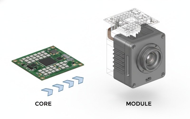
- Thermal Cores represent the raw sensor engine comprising the Focal Plane Array (FPA) and basic readout electronics, requiring significant integration effort.
- Thermal Modules are semi-finished subsystems including lenses, advanced image processing, and standard interfaces like USB or GigE.
- Development Time is significantly reduced with modules, while cores offer maximum customization for SWaP-constrained applications like UAV payloads.
- Cost Architecture favors cores for high-volume production, whereas modules reduce NRE (Non-Recurring Engineering) costs for smaller batches.
Defining the Infrared Imaging Architecture
To make an informed procurement decision, engineers must first establish the precise definitions of these components within the context of Uncooled VOx (Vanadium Oxide) Microbolometer technology. The industry standard definition relies on the level of signal processing and hardware encapsulation provided.
The Fundamentals of Thermal Camera Cores
A thermal camera core is the heart of any infrared system. It generally consists of the Focal Plane Array (FPA) sensor—usually a VOx or Amorphous Silicon microbolometer—bonded to a Read-Out Integrated Circuit (ROIC). The core includes the bare minimum electronics required to power the sensor and output raw digital data.
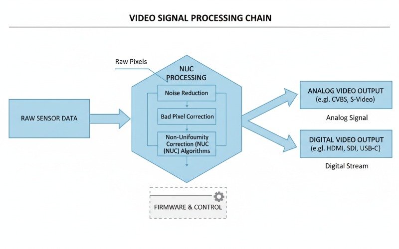
Cores are typically supplied without a lens, although a lens mount or holder may be attached. The data output is often raw 14-bit digital video (such as CMOS parallel or MIPI CSI-2) that requires downstream processing. This processing includes Non-Uniformity Correction (NUC), Bad Pixel Replacement (BPR), and dynamic range compression. The core is designed for deep integration where the system integrator takes responsibility for the optical path and final image signal processing pipeline.
The Scope of Thermal Imaging Modules
A thermal imaging module represents a higher level of functional completeness. A module integrates the core described above with a specific objective lens, a housing structure, and a processing board that handles the image correction algorithms onboard. The output from a module is typically a processed video stream ready for display or analysis.
Modules utilize standard communication protocols such as USB-UVC, Camera Link, or GigE Vision. They come factory-calibrated with the specific lens attached, meaning the NUC tables are optimized for that optical assembly. This “plug-and-play” nature makes modules ideal for industrial automation, security systems, and handheld device prototyping where optical engineering expertise may be limited.
Engineering Differences Between Cores and Modules
The transition from core to module involves specific engineering trade-offs impacting Size, Weight, and Power (SWaP), as well as mechanical rigidity and thermal management.
Optical Interface and Lens Mounts
Optical integration is often the primary differentiator. When purchasing a thermal core, the integrator is responsible for selecting a lens that matches the FPA’s pixel pitch (e.g., 12μm or 17μm) and resolution. The integrator must also handle the precise mechanical alignment of the lens to the sensor plane. A misalignment of even a few microns can result in blurring or optical aberrations that degradation NETD (Noise Equivalent Temperature Difference) performance.
Conversely, thermal modules arrive with the lens mounted and focused at infinity or a specific working distance. The lens is typically athermalized, meaning it maintains focus across the operating temperature range (-40°C to +80°C). For applications requiring rapid deployment or ruggedization against shock and vibration, the pre-aligned assembly of a module mitigates significant risk.
Signal Processing and Video Outputs
Signal processing capability dictates the complexity of the host system. Thermal cores output raw data. This data is linear and contains the full radiometric dynamic range, but it is visually unappealing and technically challenging to manage. The host processor (FPGA or SoC) must apply gain and offset maps to correct for sensor non-uniformity.
Modules perform these calculations internally. They often include features like Digital Detail Enhancement (DDE) or histogram equalization to produce high-contrast analog (CVBS) or digital video. For thermography applications, modules can output temperature-linear data where each pixel value corresponds to a specific temperature, significantly simplifying software development for radiometric analysis.
Integration Complexity and Time to Market
The choice between a thermal module vs thermal core directly correlates to the engineering resources available and the target time to market.
Hardware Integration Challenges
Hardware integration for a thermal core requires custom PCB design. You must design a board to supply precise voltages to the ROIC, manage clock signals, and route high-speed digital data lines without introducing noise. The physical mounting of the bare core also requires careful thermal management design to dissipate heat from the FPGA and sensor, ensuring the sensor temperature remains stable for accurate readings.
Modules alleviate this burden. They typically feature standard connectors (e.g., USB-C, RJ45, or industrial Hirose connectors) and have built-in power regulation circuits. A module can often be bolted directly into a system enclosure with minimal concern for electromagnetic interference (EMI) or heat sinking, as the module chassis acts as a thermal mass.
Software Development Kits and Calibration
Software integration is equally distinct. Working with a core necessitates writing drivers to interpret raw data frames and applying calibration coefficients. If the system includes a mechanical shutter for NUC, the integrator must write the control logic to trigger the shutter based on sensor temperature drift.
Modules are generally supported by comprehensive SDKs (Software Development Kits) compatible with Windows, Linux, or Android. These SDKs provide high-level function calls to get an image, read a temperature at a specific coordinate, or change color palettes. This abstraction layer allows software teams to focus on application logic rather than low-level image processing.
Selecting the Right Solution for Your Application
The decision matrix depends heavily on volume and application constraints.
Choose a Thermal Core When:
- Volume is High: In productions exceeding 1,000 units per year, the lower unit cost of a core outweighs the higher NRE.
- SWaP is Critical: For drone payloads or wearable sights, the extra weight and bulk of a module housing are unacceptable.
- Custom Optics are Required: If the application needs a specialized dual-FOV or continuous zoom lens, a core provides the necessary mechanical freedom.
Choose a Thermal Module When:
- Time to Market is Priority: You need a working prototype or product in weeks, not months.
- Engineering Resources are Limited: Your team lacks specialized FPGA developers or optical engineers.
- Ruggedization is Necessary: The application requires an industrial-grade enclosure that is already shock and IP-rated.
Technical Specification Comparison
The following table outlines the technical divergence between a standard OEM thermal core and a fully integrated thermal module.
| Feature | Thermal Camera Core | Thermal Imaging Module |
|---|---|---|
| Output Format | Raw Digital (14-bit CMOS/MIPI) | Processed Video (Analog/HDMI/USB) |
| Optics | None (Sensor Only) or Lens Mount | Integrated, Focused, Athermalized Lens |
| Calibration (NUC) | Requires System Level Calibration | Factory Calibrated |
| Radiometry | Raw Counts (Requires conversion) | Temperature Linear (Direct readout) |
| Power Supply | Specific Voltage Rails (e.g., 3.3V, 1.8V) | Wide Input Range (e.g., 5V – 24V) |
| Integration Effort | High (Hardware + Firmware + Optics) | Low (Mechanical + API) |
| Typical NETD | <40mK (Dependent on integration) | <40mK (System level verified) |
Frequently Asked Questions
Can I attach any lens to a thermal core?
Is a shutterless core better than a shuttered module?
Do thermal modules support radiometric temperature measurement?
What is the difference between cooled and uncooled cores?