
China Moneypro
Night Vision vs Thermal Imaging Technical Comparison Guide
Explore the engineering differences between night vision and thermal imaging. We analyze I2 tubes versus uncooled microbolometers for detection performance.
This article is part of our Comparisons & Buying Guides section. For a complete overview, visit our Knowledge Hub guide.
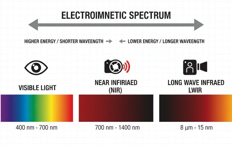
Selecting the right optical system for low-visibility environments requires a fundamental understanding of the electromagnetic spectrum. The debate between night vision vs thermal imaging is not merely about preference but about the physics of photon detection. As an optoelectronics engineer, I often see confusion regarding how these two distinct technologies interpret the world. One amplifies visible light while the other detects infrared radiation emitted as heat.
This technical guide dissects the operational mechanics of Image Intensification (I2) and Infrared Thermal Imaging. We will analyze the sensor architecture, spectral response, and tactical advantages of each system to help you determine the superior solution for your specific application.
Key Takeaways for Electro Optical Systems
- Spectral Difference
Night vision amplifies reflected photons in the Near-Infrared (NIR) spectrum (0.7µm – 1.0µm), while thermal imaging detects emitted radiation in the Long-Wave Infrared (LWIR) spectrum (8µm – 14µm). - Light Dependency
Image Intensification (I2) requires some ambient light or active IR illumination to function. Thermal imaging is completely passive and operates in total darkness. - Atmospheric Penetration
Thermal sensors offer superior performance through obscurants like fog, smoke, and foliage due to longer wavelengths. - Sensor Architecture
Night vision uses vacuum tubes with photocathodes and microchannel plates. Thermal imaging uses solid-state Focal Plane Arrays (FPA) made of Vanadium Oxide or Amorphous Silicon.
Principles of Image Intensification Technology
Night vision technology, technically known as Image Intensification (I2), operates on the principle of photon amplification. It captures the small amount of ambient light present in an environment—from starlight, moonlight, or distant city glow—and amplifies it thousands of times to produce a visible image.
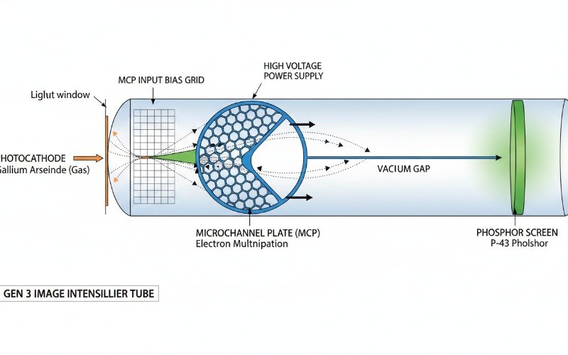
The core component of a night vision device is the Image Intensifier Tube. This vacuum tube executes a multi-stage photoelectric conversion process.
The Photocathode Conversion Process
Light photons enter the objective lens and strike the photocathode. In modern Generation 3 devices, this photocathode is typically composed of Gallium Arsenide (GaAs). When photons impact the GaAs layer, energy is transferred to electrons, causing them to be ejected into the vacuum tube. This is the photoelectric effect in action.
Microchannel Plate Amplification
The released electrons pass through a Microchannel Plate (MCP). The MCP is a thin glass disc containing millions of microscopic channels. As electrons enter these channels, they strike the channel walls, releasing secondary electrons in a cascading avalanche effect. For every single electron that enters, thousands exit. This gain mechanism is what allows the device to see in near-total darkness.
Finally, these multiplied electrons strike a phosphor screen, converting the electron energy back into visible photons, typically creating the signature green or white monochrome image associated with night vision.
Physics of Thermal Infrared Detection
Thermal imaging operates on entirely different physics. It does not rely on reflected light. Instead, it detects thermal radiation emitted directly by objects. All objects above absolute zero (-273.15°C) emit infrared radiation. The intensity of this radiation increases with the object’s temperature.
Most commercial and industrial thermal cameras utilize uncooled microbolometer sensors. These sensors detect radiation in the Long-Wave Infrared (LWIR) band, typically between 8µm and 14µm.
Uncooled Microbolometer Architecture
The heart of a thermal camera is the Focal Plane Array (FPA). The FPA consists of an array of pixels, each containing a microbolometer. The sensing material is usually Vanadium Oxide (VOx) or Amorphous Silicon (a-Si). When infrared radiation strikes the microbolometer, the material heats up, causing a measurable change in its electrical resistance.
Readout Integrated Circuits (ROIC) measure this resistance change across the entire array and convert it into a video signal. The result is a thermogram—a visual representation of temperature differences.
Because this process detects heat rather than light, thermal imagers are completely immune to darkness. A thermal camera will produce the exact same image at high noon as it does at midnight, assuming the thermal contrast of the scene remains constant.
Operational Performance Comparison
When engineering an optical solution, we evaluate performance based on Detection, Recognition, and Identification (DRI) standards. The choice between night vision vs thermal imaging depends heavily on the environmental conditions and the specific goal of the user.
Target Detection Capability
Thermal imaging is vastly superior for detection. A living being or a running engine generates a high thermal contrast against a cooler background. A thermal sensor with a Noise Equivalent Temperature Difference (NETD) of less than 40mK can detect a human signature from kilometers away, even if that person is camouflaged or hiding in deep shadows.
Night vision relies on contrast provided by reflected light. If a target wears camouflage that blends with the foliage in the Near-IR spectrum, they effectively vanish to an I2 sensor. However, night vision provides better resolution for identification once the target is close.
Environmental Obscurants
Atmospheric conditions affect visible light and Near-IR significantly more than LWIR. Fog, smoke, and heavy rain scatter visible light photons, rendering night vision goggles ineffective. The longer wavelengths of thermal radiation can penetrate smoke and light fog with much greater efficiency, maintaining situational awareness in adverse weather.

Technical Specifications Comparison Matrix
The following table outlines the critical engineering differences between standard Gen 3 Night Vision and Uncooled VOx Thermal Imaging systems.
| Feature | Night Vision (Image Intensification) | Thermal Imaging (Uncooled LWIR) |
|---|---|---|
| Primary Technology | Vacuum Tube (Photocathode/MCP) | Microbolometer FPA (VOx / a-Si) |
| Spectral Range | 0.7µm – 1.0µm (Near-IR) | 8µm – 14µm (Long-Wave IR) |
| Light Requirement | Requires ambient light or IR illuminator | Zero light required (Passive) |
| Through Glass | Yes, functions through standard glass | No, blocked by glass (Requires Germanium) |
| Camouflage Detection | Difficult (relies on visual contrast) | Excellent (relies on heat signature) |
| Battery Life | High (50+ hours typical) | Moderate (5-10 hours typical) |
| Image Output | Real-world visual representation | False-color or Monochrome heat map |
Limitations and Engineering Challenges
While thermal imaging offers distinct advantages in detection, it suffers from specific optical limitations. The primary engineering challenge is optics material. Standard silicate glass is opaque to LWIR radiation. Therefore, thermal cameras must use lenses made of Germanium, Chalcogenide glass, or Zinc Selenide. These materials are expensive and heavy.
Furthermore, thermal images are interpretative. You cannot read a license plate, see facial features clearly for biometric identification, or read signage with a standard thermal camera. The image is a representation of surface temperature, not visible reflectivity.
Night vision maintains the “natural” look of the scene. It allows for facial recognition, reading maps, and navigating through glass windows or windshields—tasks that are impossible with LWIR thermal sensors.
Future Trends in Sensor Fusion
The future of low-light optics lies in Sensor Fusion. This technology combines the optical overlay of an I2 tube with a thermal overlay. By fusing these two spectrums, operators gain the detection capabilities of thermal with the spatial resolution and identification capabilities of night vision. These systems are currently becoming standard in high-end military applications and are slowly trickling down to the commercial sector.
Common Questions on Infrared Technology
Below are authoritative answers to the most frequent technical inquiries regarding these optical systems.
Can thermal imaging see through walls
Why cannot thermal cameras see through glass
Does night vision work in absolute darkness
What is the difference between cooled and uncooled thermal cameras