
China Moneypro
How to Select Advanced EO/IR Gimbal Payloads for ISR Systems
Guide for system integrators on choosing EO/IR gimbals. Covers stabilization, MWIR vs LWIR sensors, laser rangefinders, and SWaP optimization strategies.
Integrating an Electro-Optical/Infrared (EO/IR) gimbal payload is one of the most critical architectural decisions in the design of unmanned aerial vehicles (UAVs), unmanned ground vehicles (UGVs), and fixed surveillance stations. For system integrators, the challenge lies in balancing Size, Weight, and Power (SWaP) constraints against the unyielding demand for superior range performance and image stability.
This technical guide dissects the selection process for EO/IR gimbals. We analyze the trade-offs between cooled and uncooled thermal cores, the physics of stabilization accuracy, and the integration requirements for modern mission computers.
Key Takeaways for System Integrators
- Stabilization Defines Utility: Without micro-radian level stabilization, high optical zoom is functionally useless due to jitter.
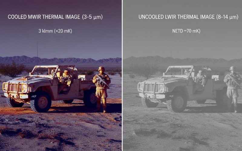
- Sensor Matching: Choose uncooled LWIR for short-range situational awareness and cooled MWIR for long-range target acquisition.
- SWaP-C Optimization: Every gram counts on a UAV. Opt for integrated systems that combine video processing and tracking onboard to reduce link bandwidth.
- DRI Standards: Base your sensor selection on Johnson’s Criteria for Detection, Recognition, and Identification ranges rather than pixel count alone.

Understanding Gimbal Stabilization Accuracy
The primary function of a gimbal is not merely to hold sensors but to isolate them from platform vibration and movement. In high-magnification applications, even micro-vibrations result in significant image blur and target shifting. This is quantified by stabilization accuracy, typically measured in micro-radians (µrad).
For tactical applications requiring human identification at 5 kilometers, a stabilization accuracy of better than 50 µrad is standard. High-end systems utilizing fiber-optic gyroscopes (FOG) or MEMS gyroscopes with advanced Kalman filtering can achieve stabilization below 20 µrad. Integrators must verify that the specified accuracy applies to the entire operational frequency range of the vehicle vibration profile.
Direct Drive versus Geared Motors
Direct drive brushless DC (BLDC) motors offer superior response times and eliminate the backlash associated with geared systems. For long-range surveillance requiring precise pointing and tracking, direct drive is the preferred mechanism. Geared systems may offer higher torque for heavier payloads but often introduce mechanical hysteresis that complicates fine-tune stabilization algorithms.
Thermal Sensor Selection Criteria
The infrared core is the most expensive and complex component of an EO/IR gimbal payload. The choice between Long-Wave Infrared (LWIR) and Mid-Wave Infrared (MWIR) dictates the operational capability of the system.
Uncooled LWIR VOx Microbolometers
Uncooled Vanadium Oxide (VOx) sensors operate in the 8-14 µm spectral range. They are solid-state devices requiring no cryogenic cooler, making them lighter, more reliable, and less power-hungry. Modern 12µm pixel pitch sensors allow for smaller optics while maintaining resolution.
These sensors are ideal for Class 1 and Class 2 UAVs where weight is premium. However, their sensitivity (NETD) typically hovers around 40-50mK, and they are diffraction-limited, meaning they struggle with identification at ranges exceeding 2-3 kilometers.
Cooled MWIR Detectors
For missions requiring identification at 5km, 10km, or beyond, Cooled MWIR (3-5 µm) is mandatory. These detectors use a Stirling cryocooler to lower the sensor temperature to roughly 77 Kelvin. This minimizes thermal noise, achieving NETD values often below 25mK.
Because the 3-5 µm wavelength is smaller than LWIR, the optical diffraction limit is lower, allowing for sharper images at extreme magnifications. Integrators must account for the “cool-down time” (typically 3-7 minutes) and the finite lifespan of the cooler assembly (typically 10,000 to 20,000 hours).
EO Camera and Optical Zoom Requirements
The visible light (EO) camera provides daytime situational awareness. While 4K resolution is becoming common, optical zoom capability remains the priority for ISR missions. Digital zoom degrades image quality, whereas optical zoom maintains pixel density.
A 30x continuous optical zoom is a standard baseline for tactical gimbals. For superior performance, look for global shutter sensors rather than rolling shutter sensors. Rolling shutters can introduce “jello effects” or image skewing when the gimbal moves quickly or experiences high-frequency vibration.
Technical Comparison of Sensor Architectures
| Feature | Uncooled VOx (LWIR) | Cooled MCT/InSb (MWIR) |
|---|---|---|
| Wavelength | 8 – 14 µm | 3 – 5 µm |
| NETD Sensitivity | <40 mK | <25 mK |
| Pixel Pitch | 12µm / 17µm | 10µm / 15µm |
| DRI Range (Human) | ~1.5 km (Detection) | >10 km (Detection) |
| SWaP Impact | Low (Lightweight) | High (Requires Cooler) |
| Cost | Low to Moderate | High |
Laser Rangefinders and Target Tracking
Modern ISR missions require more than just viewing a target. They require geo-location. This demands a Laser Rangefinder (LRF) integrated into the optical bench. The LRF fires a pulse to measure distance, which the onboard processor combines with the gimbal’s azimuth and elevation angles to calculate the target’s GPS coordinates.
For accurate targeting, an eye-safe 1535nm or 1550nm laser is preferred over 1064nm lasers, which are detectable by night vision equipment and can be hazardous to eyesight. Furthermore, ensure the gimbal supports object tracking. Correlation trackers and centroid trackers allow the gimbal to automatically follow a moving vehicle or person, reducing operator workload.
Data Interfaces and Control Protocols
Integration speed depends on interface compatibility. The physical video output must match the mission computer’s capabilities. SDI and HDMI are standard for low-latency raw video, while Ethernet (IP Video) is preferred for networked systems that require H.264/H.265 compression for downlink.
Control protocols are equally vital. While proprietary protocols exist, standard sets like VISCA, Pelco-D, or the UAV-centric MAVLink protocol simplify integration with autopilots like Pixhawk or Cube. Verify that the gimbal manufacturer provides a comprehensive SDK or API for custom software development.
Frequently Asked Questions
What is the difference between 2-axis and 4-axis stabilization?
Does pixel pitch matter for thermal imaging range?
Why is NETD important for surveillance?