
China Moneypro
EO IR Integration Differences for UAV and Ground Vehicles
Discover critical engineering differences in UAV vs vehicle EO/IR integration. Explore SWaP constraints, stabilization protocols, and sensor selection strategies.
System integrators face distinct engineering challenges when deploying Electro-Optical/Infrared (EO/IR) payloads across different domains. While the fundamental physics of thermal imaging remains constant, the environmental and operational constraints of Unmanned Aerial Vehicles (UAVs) versus Ground Combat Vehicles (GCVs) necessitate radically different integration strategies.
For aerial platforms, every gram impacts flight time and center of gravity. Conversely, ground platforms demand ruggedization capable of surviving ballistic shock and continuous low-frequency vibration. This technical analysis explores the specific architectural differences required to successfully integrate high-performance imaging modules into these contrasting environments.

Key Takeaways for System Engineers
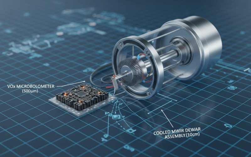
- SWaP Constraints: UAVs prioritize weight reduction using uncooled VOx microbolometers, while vehicles accommodate heavier cooled MWIR systems for long-range target acquisition.
- Stabilization Profiles: Aerial systems fight high-frequency propeller vibration requiring 3-axis micro-gimbals. Ground systems combat high-amplitude shock requiring robust pan/tilt units.
- Power Architecture: UAVs utilize clean DC battery power with strict consumption limits. Ground vehicles require protection against dirty power and voltage spikes per MIL-STD-1275.
- Data Interfaces: UAVs lean toward MIPI CSI-2 and LVDS for low latency and low mass. Ground vehicles utilize GigE Vision and HD-SDI for ruggedized, long-cable routing.
SWaP Constraints Define the Sensor Selection
Size, Weight, and Power (SWaP) remains the primary governing factor in UAV gimbal payload. For Class 1 and Class 2 UAVs, the payload capacity is often limited to under 2kg. This necessitates the use of uncooled Long-Wave Infrared (LWIR) sensors. Modern Vanadium Oxide (VOx) microbolometers with a 12μm pixel pitch allow for smaller germanium optics without sacrificing range. A 12μm sensor creates a narrower field of view (FOV) than a 17μm sensor using the same lens, effectively increasing the drift-range performance per gram of optical glass.
Ground vehicles often have payload capacities exceeding 50kg for the remote weapon station (RWS) or commander’s independent viewer (CIV). This allows integrators to deploy Cooled Mercury Cadmium Telluride (MCT) or Indium Antimonide (InSb) Mid-Wave Infrared (MWIR) detectors. These systems require a cryogenic cooler (Dewar assembly) which adds significant weight and power draw but delivers superior thermal sensitivity (NETD < 25mK) and effectively penetrates high humidity environments.
Stabilization Mechanics and Vibration Damping
The vibration profiles of aerial and ground platforms are diametrically opposed, forcing integrators to select platform-specific gimbal architectures.
UAV High Frequency Vibration Mitigation
UAVs, particularly multi-rotors, generate high-frequency micro-vibrations from motor rotation and propeller wash. If left unmanaged, this results in “jello effect” or rolling shutter artifacts in the video feed. Integration requires soft-mount wire rope isolators tuned to the specific resonant frequency of the airframe. The gimbal itself typically employs direct-drive brushless motors with high-bandwidth control loops to correct for pitch and roll deviations instantly.
Ground Vehicle Shock and Recoil Management
Ground vehicles experience low-frequency, high-amplitude shocks from terrain negotiation and potentially extreme G-force spikes from main gun recoil. Soft mounts used in UAVs would be disastrous here, causing the sensor to sway uncontrollably. Ground integration demands rigid mounting interfaces or stiff elastomeric dampers. The EO/IR housing must be hardened to meet MIL-STD-810G standards for ballistic shock. Vehicle mounted thermal camera focuses on maintaining a fixed horizon line while the hull pitches beneath it, often utilizing 2-axis stabilization with a larger torque overhead to resist wind drag and mud accumulation.
Power Regulation and Electrical Standards
The electrical environment inside a vehicle is notoriously “dirty.” Power is typically supplied by an alternator connected to a lead-acid or Li-ion battery bank, operating at a nominal 24V or 28V. However, engine cranking can cause voltage drops, and load dumps can create spikes exceeding 100V. EO/IR modules integrated into vehicles must utilize robust DC-DC converters compliant with MIL-STD-1275 to filter these transients. Failure to isolate the sensitive Focal Plane Array (FPA) readout integrated circuits (ROIC) from these spikes will result in permanent sensor damage.
UAV power supplies are comparatively clean, usually drawing directly from a LiPo battery via a Power Distribution Board (PDB). The challenge here is total power consumption (SWaP-C). Every watt consumed by the payload reduces flight endurance. Integrators must prioritize sensors with low steady-state power consumption. Uncooled systems typically draw <2W, whereas a cooled MWIR system for a vehicle may draw 10W to 20W just to maintain cryogenic cooling temperatures.
Data Interface and Cabling Requirements
Signal integrity and cable mass drive the selection of data interfaces.
- UAV Interfaces: To minimize weight, UAV integrators prefer ribbon cables and interfaces like MIPI CSI-2 or parallel LVDS. These allow for raw digital video transfer directly to an onboard compute module (like an NVIDIA Jetson) for edge processing. Connectors are often delicate, high-density types (e.g., Molex Pico-Clasp).
- Vehicle Interfaces: Weight is less critical than durability. Ground systems utilize shielded Ethernet cables (GigE Vision), HD-SDI (coaxial), or Camera Link. These cables can run for several meters through a turret slip ring without signal degradation. Connectors are invariably ruggedized circular types, such as MIL-DTL-38999 or LEMO series, designed to withstand water ingress (IP67) and mechanical stress.
Detailed Technical Comparison
| Feature | UAV Integration | Ground Vehicle Integration |
|---|---|---|
| Primary Sensor Type | Uncooled VOx Microbolometer (LWIR) | Cooled MCT/InSb (MWIR) or Uncooled LWIR |
| Pixel Pitch | 10μm – 12μm (Reduces Lens Size) | 15μm – 25μm (Optimizes Sensitivity) |
| Vibration Profile | High Frequency, Low Amplitude | Low Frequency, High Amplitude (Shock) |
| Stabilization | 3-Axis Direct Drive Micro-Gimbal | 2-Axis Pan/Tilt or Slew-to-Cue Turret |
| Power Source | Clean Battery DC (Limited Wattage) | Dirty Alternator/Bus (MIL-STD-1275) |
| Data Standard | MIPI CSI-2, LVDS, USB 3.0 | GigE Vision, HD-SDI, Analog (Legacy) |
| Environmental Rating | IP54 (Weight dependent) | IP67 / MIL-STD-810 Sand & Dust |
Optical Range and Environmental Factors
The operational altitude of a UAV provides a natural advantage in line-of-sight, but atmospheric attenuation differs. UAVs look through a vertical column of air which may have different thermal gradients than the horizontal path used by ground vehicles. Ground vehicles must contend with ground-level obscurants such as dust, smoke, and high humidity.
Consequently, vehicle optics often require integrated wiper systems or hard-carbon coatings (DLC) to prevent abrasion from sand and mud. UAV optics are rarely equipped with wipers due to weight but may require hydrophobic coatings to shed rain droplets during flight. For long-range identification (DRI criteria), ground vehicles can accommodate large focal length lenses (e.g., 100mm to 300mm continuous zoom), whereas UAVs typically rely on fixed focal lengths (e.g., 25mm to 75mm) to maintain stability limits.
Frequently Asked Questions
Can I use a vehicle-rated thermal camera on a drone
Why is Cooled MWIR preferred for ground vehicles
What is the standard for ruggedizing vehicle EO IR systems
For deeper consultation on selecting the correct VOx or MCT sensor module for your specific platform integration, contact our engineering support team.