
China Moneypro
Electro Optical Imaging Limitations
This article is part of our EO Technology section. For a complete overview, visit our Knowledge Hub guide.
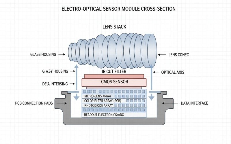
Electro-optical (EO) sensors remain the backbone of global surveillance and reconnaissance architectures. From standard CMOS sensors in commercial drones to advanced CCD arrays in aerospace defense, visible light imaging provides unparalleled resolution and color contrast for target identification. However, relying exclusively on EO payloads creates critical vulnerabilities in mission-critical environments.
For system integrators and defense manufacturers, understanding the physics-based boundaries of the visible spectrum is essential for designing robust electro-optical/infrared (EO/IR) platforms. A payload that performs flawlessly in clear daylight may become operationally useless during maritime haze, heavy obscurants, or zero-light conditions.
This technical analysis dissects the inherent limitations of electro-optical imaging systems. We examine atmospheric physics, photon starvation, and the strategic necessity of multi-spectral sensor fusion.
Key Takeaways for Engineering Teams
- Atmospheric Scattering: Visible light wavelengths (0.4–0.7µm) succumb to Rayleigh and Mie scattering significantly more than IR wavelengths, reducing range in fog and haze.
- Photon Starvation: Silicon-based EO sensors require external illumination; performance degrades exponentially as ambient light drops below 0.1 lux without active NIR illumination.
- Visual Camouflage Vulnerability: EO systems rely on visual contrast, making them susceptible to standard camouflage patterns that thermal imaging would easily defeat.
- Multi-Sensor Necessity: Modern ISR requirements mandate integrating EO with MWIR or LWIR cores to ensure 24/7 operability.
Atmospheric Attenuation and Scattering Physics
The most significant operational limitation of electro-optical imaging lies in its interaction with the atmosphere. While vacuum performance is determined by optics and sensor quantum efficiency (QE), real-world performance is dictated by atmospheric transmission windows.
Rayleigh and Mie Scattering Effects
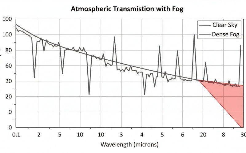
Visible light occupies the 0.4 to 0.7-micron band. This short wavelength makes it highly susceptible to scattering by airborne particles. According to the physics of scattering, when particle size is comparable to the wavelength of the radiation (Mie scattering), attenuation is maximized.
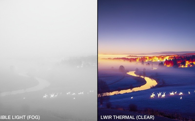
In environments with fog, smoke, or maritime haze, water droplets and particulate matter often range from 0.5 to 10 microns. This creates a “whiteout” effect for EO sensors. The signal-to-noise ratio (SNR) drops as the backscattered light overwhelms the target signal. In contrast, Long-Wave Infrared (LWIR) sensors operating at 8–14 microns can often bypass these particles effectively, as the wavelength is larger than the scattering media.
Dependency on External Illumination
Electro-optical systems are passive reflected-energy sensors. They do not detect intrinsic energy emitted by the target (unlike thermal imagers) but rather detect photons reflected off the target from an external source, typically the sun or artificial lighting.
Low Light Performance Constraints
While Low-Light Level (LLL) CMOS and EMCCD technologies have advanced, they are fundamentally bound by the availability of photons. In conditions classified as “overcast starlight” or deep tunnel environments, the ambient lux levels drop below the threshold required to generate a usable photoelectric current in the silicon substrate.
Integrators often attempt to mitigate this by adding Near-Infrared (NIR) illuminators (850nm or 940nm). However, this introduces new tactical limitations:
- Power Consumption: Active illumination drains power budgets in SWaP-constrained systems like UAVs.
- Signature Reveal: Active NIR illumination is invisible to the naked eye but acts as a bright beacon to adversaries equipped with basic night vision capability.
- Range Gating: Illuminators have limited range, often failing to match the zoom capabilities of the optical lens assembly.
Visual Contrast and Camouflage Vulnerabilities
Target acquisition algorithms in EO systems rely heavily on contrast detection—specifically, the difference in luminance or color between the target and the background. This reliance makes EO systems the primary victim of camouflage techniques.
Standard military camouflage is designed specifically to disrupt the visual outline and blend with the background color palette in the visible spectrum. A green vehicle in a forest is difficult for an EO sensor to segment. Furthermore, shadows and complex urban textures can confuse autofocus algorithms and automated object detection models utilizing visual data.
Technical Comparison of Spectral Bands
To justify the integration of supplementary sensor technologies, engineers must quantify the performance gap between EO and infrared bands. The table below outlines the operational boundaries.
| Feature | Visible EO (0.4-0.7µm) | SWIR (0.9-1.7µm) | LWIR Thermal (8-14µm) |
|---|---|---|---|
| Resolution | Extremely High (HD/4K) | High | Medium (VGA/XGA) |
| Daytime Performance | Excellent (Color) | Excellent | Good |
| Total Darkness | Fails (Needs Illum) | Poor (Needs Glow) | Excellent (Passive) |
| Fog/Smoke Penetration | Very Poor | Moderate | Excellent |
| Glass Transmission | Yes | Yes | No (Needs Ge/ZnSe) |
| Target Identification | Facial Rec Capable | Facial Rec Possible | Classification Only |
Overcoming Limits via Multi Sensor Fusion
The limitations of EO imaging do not render it obsolete; rather, they dictate the necessity of sensor fusion. Modern gimbal payloads and fixed surveillance systems utilize a “best of both worlds” approach.
EO and IR Overlay
By blending the high-spatial-frequency data (edges and textures) from the EO sensor with the thermal intensity data from a VOx microbolometer, systems can provide situational awareness that neither sensor can achieve alone. The EO sensor provides the text on a sign or the color of a vehicle, while the thermal sensor highlights the heat signature of the engine or concealed weaponry.
Strategic Procurement Considerations
For B2B integrators sourcing camera modules, recognizing EO limits impacts component selection. High-zoom EO blocks are essential for long-range identification (DRI standards), but they must be paired with low-NETD thermal cores to guarantee detection.
When defining requirements for border security, maritime patrol, or drone inspection, the inability of EO sensors to penetrate obscurants or operate passively at night must be listed as a critical risk factor. This risk drives the budget allocation toward dual-sensor or tri-sensor (EO/IR/SWIR) configurations.
Frequently Asked Questions
Why does visible light fail in fog compared to thermal imaging?
Can high ISO settings compensate for total darkness in EO sensors?
What is the benefit of SWIR over standard EO sensors?
Is thermal imaging always superior to EO imaging?
Discover more information about EO Technology: